|
SEAVAX WIND TURBINES TEST RIG
ABOUT - CLIMATE CHANGE - CONTACTS - CROWDFUNDING - DONATE - FOUNDATION - OCEAN CLEANUP - HOME - A-Z INDEX ARRAYS - BOOM - MASTS - INTERIOR - PAINTING - ROBOTICS - WELDING - WIND TURBINES
HYDRAULICS - This experimental rig uses three double valve/solenoid dc power packs operating at 24 volts to supply four double acting rams and two rotational motors. The rams are to move the mast and tilt mechanism, operating in balanced pairs, while the motors are to turn two solar panel arrays independently so as to be able to track the sun. Commercial sun tracking devices are available, but nothing to rotate an array from a base hinge to encompass such a wide angle variation - and folding of the arrays for storm protection at sea. For this part of the project we are not concerned with sun tracking, but need to have the frame ready to accept such technology when we get to that stage.
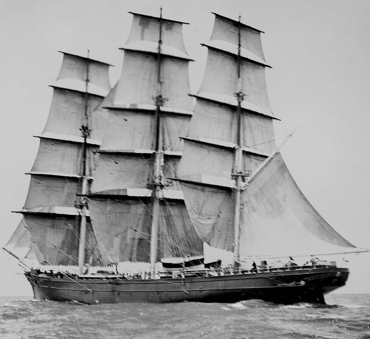
ROBOTIC TRACKING SYSTEM - Generally speaking, wind generators at sea work much better when raised into faster moving air higher above sea level, and above deck obstructions. This is known to all sailors and that is why the sailing ships of old were called "Tall Ships." The taller the mast, the more speed for the boat, it also being practical to go up rather than sideways where roll might dunk a low-level beam sail.
The windgens in this experiment are to work in conjunction with three solar arrays, one fixed and two moving to track the sun. We started off looking at the efficiency obstruction of twin turbines on a single axis. It could be that twin turbines in such an arrangement at sea might suffer little in terms of interference when a vessel is following the trade wind routes, in other words sailing downwind. Such information will not be proven at sea for quite a while. Meantime, we can run experiments using dual generators and a single, larger generator.
The twin setup is to use 2 x 400 watt generators operating at 24 volts charging two banks of batteries that will be tapped at 48 volts for draw through one of two inverters.
We will also be testing a single 2000 watt unit operating at 48 volts. The height of the assembly increases by a meter using the single unit. We need to know what the difference in side loadings is going from one configuration to another, such that when conducting tank tests at a smaller scale, we can compare results for accuracy is scaling up.
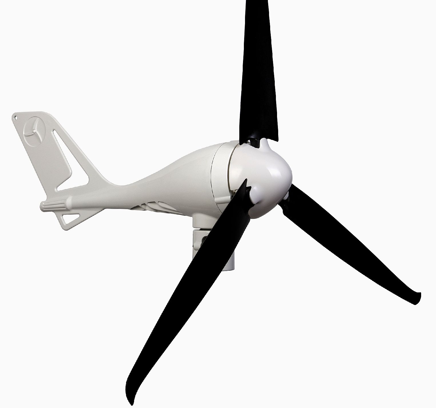
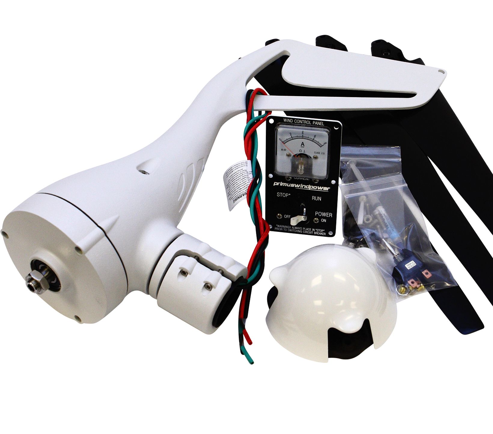
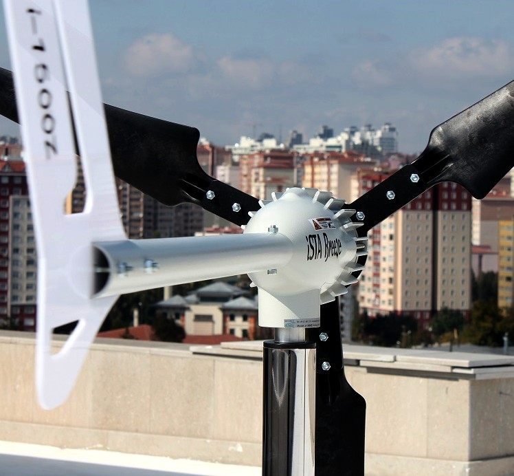
WINDGENS - This is a typical example of a 400 watt wind powered generator with a 1.2 meter blade diameter (approx) operating at 24 volts. This will be the first experiment, using two units mounted side by side. This setup is expected to be less efficient than one large generator, with the advantage of a lower (pro rata) profile that reduces roll in a vessel at sea.
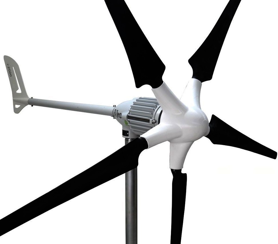
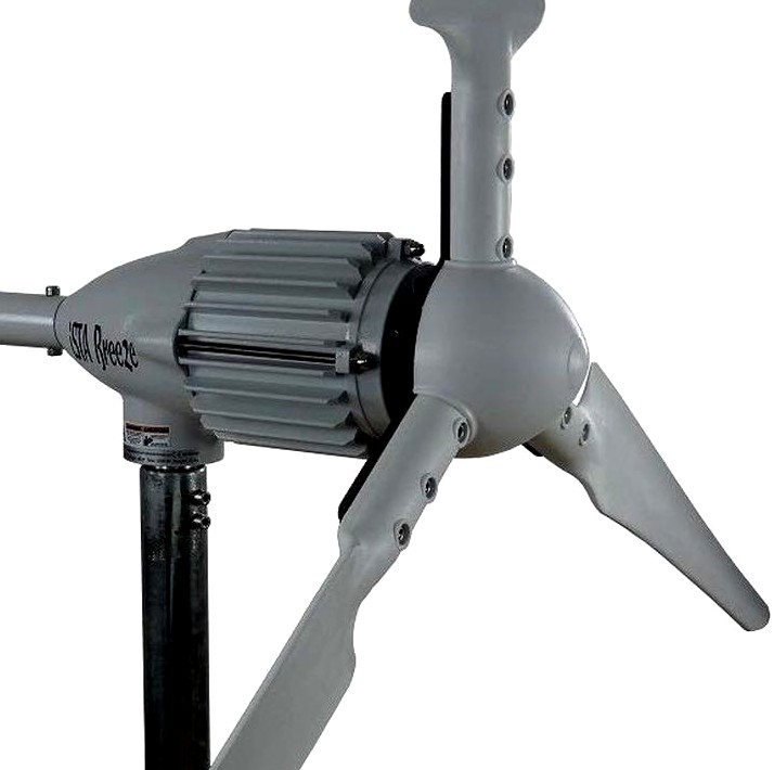
WINGEN - This is a 2000 watt wind powered generator with a 2.25 meter blade diameter, operating at 48 volts. This will be the second experiment, using just one unit. in theory we should expect to see an overall increase in efficiency. The additional roll may be overcome with an increase in reserve buoyancy. Time will tell if this is practical.
CONCEPT
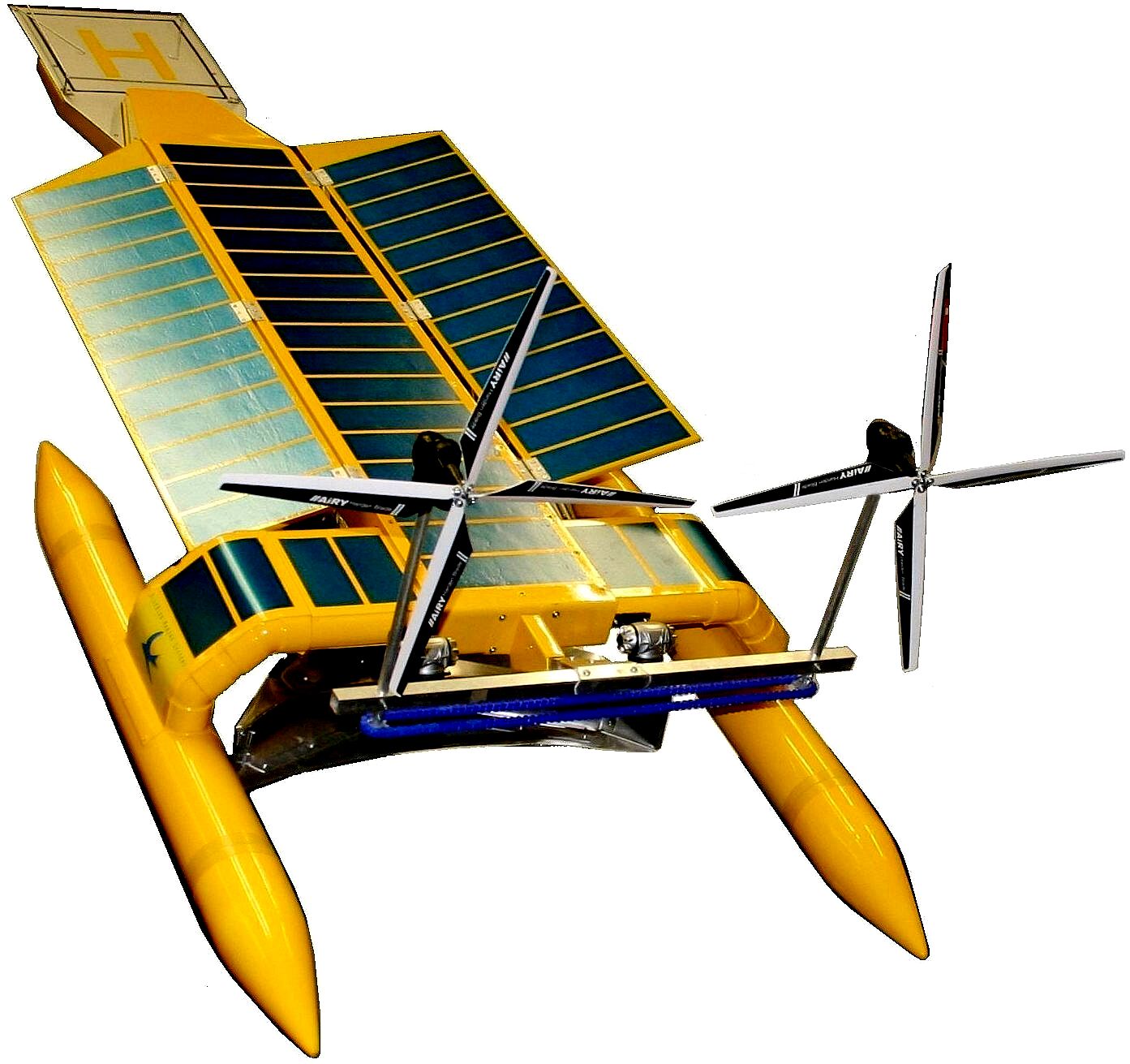
The basic premise of a SeaVax like concept is using solar and wind power together in such a way that the primary energy source, solar power, is not shaded by the secondary energy source: wind power, during daylight hours.
At night there is no solar power, but there is wind energy to capture and convert giving a working vessel a deal more power to filter water that it would otherwise not enjoy. The sailing ships of old relied on wind power alone and still managed to travel at over 15 knots peak average speeds. It makes sense then to capitalize on this free energy source when the sun is not available. Otherwise, we'd be reliant on batteries only for nighttime operations. We can also use the wind turbines during the day, provided that they don't shade the solar arrays at deck height during operations.
For example, a vessel that could advantage itself of the trade wind routes during transit, would fare rather well in terms of added performance. A workboat that did not have to travel fast, but rather stay on station, might not gain so much. But it would gain and any advantage in terms of water filtering power would speed up ocean cleaning.
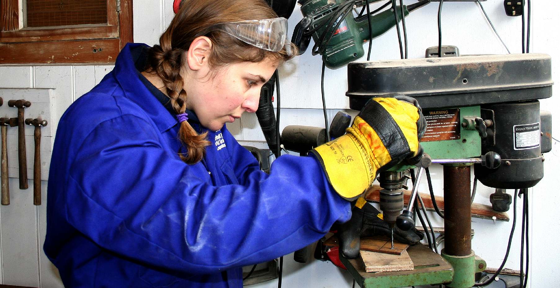
SEAVAX PROJECT DIRECTOR - Hands on, Chris tests out our new pillar drill to make a series of brackets for the Transit test rig. He liked this machine for its variable speed control and digital rpm indicator. Copyright photograph © 2 May 2019 Cleaner Ocean Foundation Ltd. All rights reserved, save for educational and research purposes.
If we accept that there is an advantage in terms of energy capture, the challenge then is how to raise high speed revolving blades into the faster moving air higher up away from the solar panels, and still be safe and in control? The question of how much of an advantage this might be below 80 meters on the sea can only be answered by practical trials. For a fleet of SeaVax it is thought that the percentage gains will provide significantly more cleaning ability on average. With large fleets being the objective, averaged performance is important.
The target we have set is 2 x 20kW turbines for SeaVax. This may translate to 1 x 20kW turbine or 2 x 10 kW turbines, but we should aim for a setup that might power a vessel at 10 knots or a close as possible. One practical difficulty is the mass of the generating head. When sourcing components we found that the mass of of generators varied considerably. The cheaper heads could be up to twice the mass of the more expensive units. This is for off the shelf technology, rather than Formula One type specialization. The blade material is also important when reducing mass is a consideration.
The Cleaner Ocean Foundation consider this to be cornerstone technology in the race to zero carbon shipping - in this case as applied to the SeaVax ocean cleaning machine and other water transports, such as the Elizabeth Swan. Zero carbon workboats make ocean cleaning a possibility. Whereas, attempting to clean oceans using diesel fuels is thought to be counter productive, where such activities would then add to climate change.
EXPERIMENTAL ECONOMICS
We needed a convenient and cost effective land based vehicle on which to develop a prototype system, before proceeding to trials at sea. We decided to mount a test rig on a Ford Transit (FT) that also doubles as one of our ocean awareness support vehicles. It's a great shame that there are no reasonably priced electric vans, where this rig is likely to harvest 110kW/hrs each week, subject to location, testing and verification.
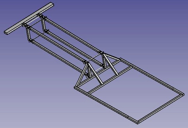
RAISED & FURLED VERSION 1 - This diagram shows a proposed test rig in draft form fitted to a transit van. We've made sure that the same rig will fit onto our Jeep (beach buggy) and will transpose to a quarter scale floating test rig that we hope to be able to float in 2020 - subject to funding. Note the height difference when raised and furled. We are hoping for significant gains in generating output from this robotic system. Copyright diagrams © 9 February 2019 Cleaner Ocean Foundation Ltd. All rights reserved, save for educational and research purposes.
PLAN VIEW VERSION 1 - This diagram shows 12 solar panels mounted on a specially built roof-rack type frame. Copyright diagrams © 9 February 2019 Cleaner Ocean Foundation Ltd. All rights reserved, save for educational and research purposes.
This is all theory at the moment, there's a lot of work to do proving the robotics and hydraulic mechanicals. You can see how the design came off the drawing board in its original form and changed as practical problems surfaced, such as which end of the Transit to have the turbines. We started with them at the rear of the van, then changed to the front for (road) safety reasons. That is what tends to happen when an idea begins to be developed, all manner of practical issues come to the fore to help you make decisions that you could not possibly have thought about before getting your hands dirty.
The FT will be equipped with two 400 watt wind turbines and twelve 150 watt solar panels, to give us 2,600 watts, feeding four 110 AH deep cycle (lead-acid) leisure batteries.
DONOR VEHICLE - This is the basic Ford Transit, as themed for awareness logistical support in 2018 by marine biologist, Emily Hoad. In effect this humble vehicle will be turned into a mobile generating unit as it harvests renewable energy during our experiments. This might be useful when working on beaches or other remote locations. Vehicles like this could provide temporary clean energy for developing third world villages for classrooms to connect to the internet. Copyright © photograph Cleaner Ocean Foundation Ltd. All rights reserved, save for educational and research purposes.
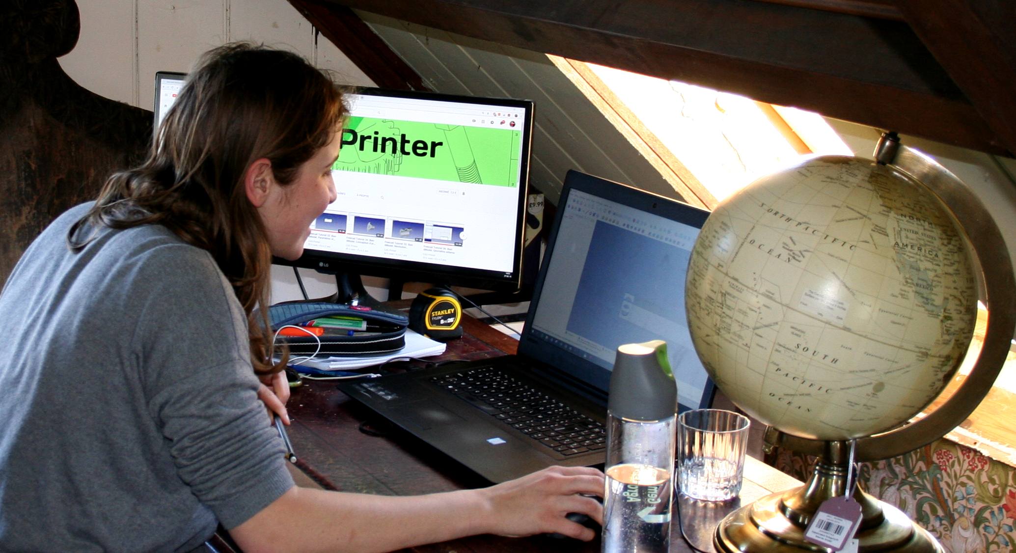
CAD - Hard at work designing the framework that will lift two 400w wind turbines roughly 3 meters higher into the air to search for more energy. Lolita D'Ortona is a student from Belgium working toward her master degree in Environmental Sciences and Technologies - Bioengineering, at Gembloux Agro-Bio Tech, Charleroi Area, Université de Liège, Belgium. She uses computer aided design software to build the steel structure in 3D for mechanical visualization of the movement and for stressing in different materials if need be. Copyright © photographs, February and March 2019. All rights reserved, Cleaner Ocean Foundation Ltd.
VERSION 2, SOLAR PANELS - The wind turbines operate in conjunction with solar panels arrays as two wings and a central deck. The solar wings can track the sun and fold over for safe storage when weather conditions are unfavourable. Copyright © diagrams, February and March 2019. All rights reserved, Cleaner Ocean Foundation Ltd.
VERSION 2, MAST & BOOM - In this diagram you can see the boom raised a little over three meters where the twin turbines should be operating in clean air. Copyright © diagrams, February and March 2019. All rights reserved, Cleaner Ocean Foundation Ltd.
Once the mechanics of the lifting mechanism is in place as a roof mounted frame, mast and boom, we need to install hydraulic rams to provide sufficient grunt to hoist the wind turbines into the air. This means using electro-hydraulic pumps to power the rams and control valves to divert the hydraulic fluid to the appropriate rams on command, via solenoid operated valves that are switched by relays. All of that controlled by a micro computer.
The commands will depend on sensors that will determine if the wind speed is high enough to warrant lift, or if the wind speed in too high, meaning that lowering of the boom will be needed to protect the wind turbines from over running that could damage the blades and burn out the generator coils.
CAD 3D SCREENSHOT - The latest computer design software allows a designer to produce a virtual product, then test the movement and calculate the material sections in relation to the loads in operation. The point loads to cope with will be at the two shaft bearings of the wind turbines, that are not shown in this diagram. Those forces will dissipate through the mounting tubes to the boom and then via the mast to the roof mounted frame. Copyright © drawing 7 March 2019. All rights reserved, Cleaner Ocean Foundation Ltd.
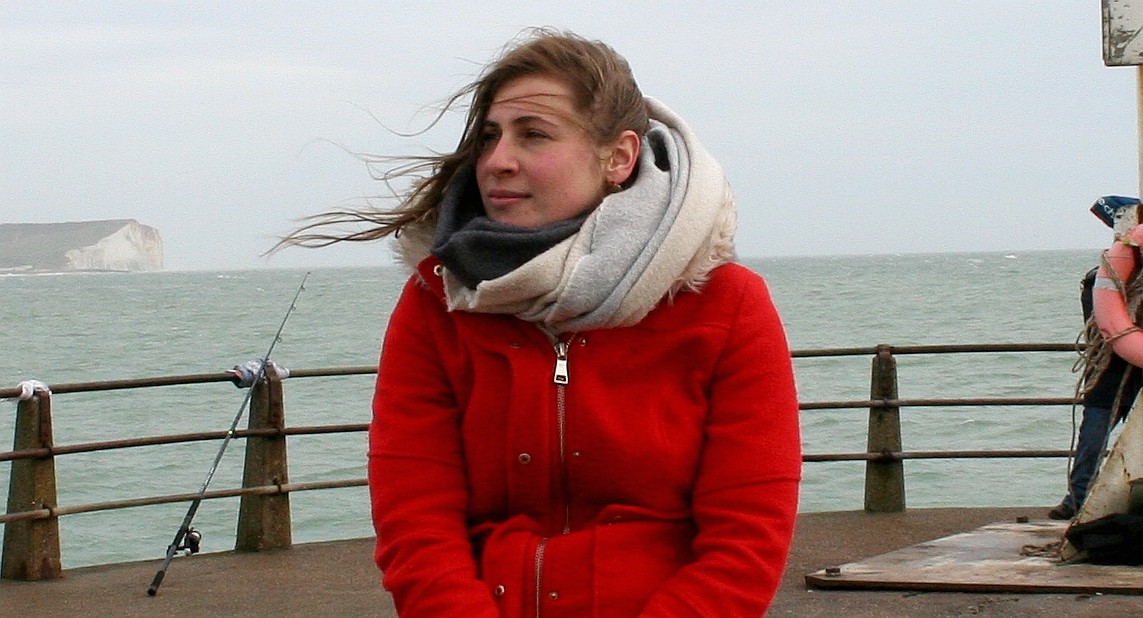
RESEARCH - Out and about getting a feel for the higher wind speeds that SeaVax will have to cope with when blue water cruising, Lolita visited Newhaven Harbour on the English coast on a blustery day when the wind speeds on the harbour jetty end were quite lively. A number of cross-channel ferries operate from this busy port. In the background you can see the white chalk cliffs known as Seaford Head. Copyright © photograph March 9 2019. All rights reserved, Cleaner Ocean Foundation Ltd.
WHAT NEXT - The test rig we hope to complete in 2019 can be taken off the Ford Transit and bolted straight onto a 1:4 scale model for use in sampling river waste and sweeping our shores to reduce plastic waste. This coastal development stage could also be used for cleaning rivers such as the Ouse at Newhaven, or even the Thames. Note that the height of the wind turbines is above the height of a person when raised. They are also far away from the deck and helm areas. Copyright © diagram March 6 2019. All rights reserved, Cleaner Ocean Foundation Ltd.
Wind power originates from differential heating of the earth by creating convection currents that move from the hottest parts of the planet (equator) to the coldest (north and south poles). Kinetic energy in the moving wind masses is converted to electric energy by the use of airfoils (blades) to create lift, attached to a spinning hub to create rotational motion. The rotational motion is then converted to electric energy via an induction generator.
• The Betz Limit represents (essentially) the maximum efficiency of a wind turbine based on fluid assumptions. It has not practically been exceeded. The maximum conversion efficiency is said to be 59.3%.
Design issues include the impact of leading wind turbines on airflow as it affects the incident flow for turbines behind them. The leading turbine(s) reduce the incident wind speed if the trailing turbines are within their wake. Logically, we might then concentrate on a single large wind turbine, save for:
1. Vessel stability issues 2.
Mass limitations of the supporting structure in practical
terms
A single large turbine does not need synchronization, another factor when it comes to complications.
REINFORCING - The loading at the front of the Ford Transit roof needed the addition of internal bracing as a frame to transfer the loads from the hydraulic rams to the chassis of the van, without which the roof would surely crumple. The steel roof frame sits on top of plywood pads to act as soft seat buffer. Inside the van we need to make a steel frame to take the loads of two hydraulic rams that will go through the roof, to lift the mast. We'll worry about waterproofing the opening later. Copyright © diagrams March 12 2019. All rights reserved, Cleaner Ocean Foundation Ltd.
STEEL FRAMES - From the drawing board to a frame made of steel. As part of this module, Lolita saw her work come to life as she worked with our fabricator to cut RHS tubing and jig the parts ready for welding. Other components were made by Picross, a local precision engineering firm in Eastbourne. Click on the picture above to see the making of these frames in more detail. Copyright © photograph April 11 2019. All rights reserved, Cleaner Ocean Foundation Ltd.
ACADEMY
- Depuis plus de 150 ans, Gembloux Agro-Bio Tech s'est imposée
comme véritable pôle d'expertise dans le domaine des
sciences du vivant et de l'ingénierie biologique.
Gembloux
Agro-Bio Tech
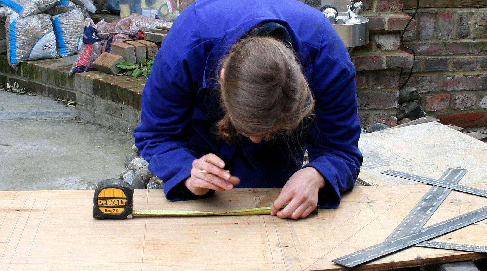
LOFTING - Taking scale drawings from the board or computer out to full size is called lofting. In this picture Lolita is plotting at full size to make a jig that will be used to ensure that the mast links are identical at the lower and upper ends of the structure. Copyright © photograph April 12 2019. All rights reserved, Cleaner Ocean Foundation Ltd.
DRILLING - Using a small pillar drill to make the bolt holes for the mounting plates. We will be using a bigger (more powerful) pillar drill to cut and ream the clevis pin mounts for the hydraulic rams. Copyright © photograph April 12 2019. All rights reserved, Cleaner Ocean Foundation Ltd.
HYDRAULICS
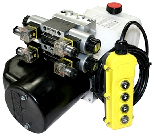
- 12V DC Double Acting, Double Solenoid Hydraulic Power Pack designed to operate two double acting cylinders independently on a variety of applications, complete with four button pendent on a 4 meter lead. This unit combines a 2.1cc/rev gear pump with a 1.6kw
electric motor with relays and
plastic motor cover. There are 4.5, 8.0, 11 or 13 Litre reservoirs with a drain plug. The
reservoir feeds via a suction strainer, return oil conveyor and filler breather.
SOLAR PANELS - Ryan helped to make sure that the solar panels will fit within the width of the Ford Transit roof with sufficient clearance for the overlapping arrays. His idea was to incorporate a sliding rearward extension to complete the roof frame. A good idea. In the end we elected to extend the frame and include another bearing mount to spread the load and make sun tracking more efficient. Copyright photograph © 22-04-19 Cleaner Ocean Foundation Ltd, all rights reserved.
SUBFRAME - Aligning the mini-tower that carries the lower mounting points for the four main mast tubes that will, in effect, become a mini crane. Here the assembly is seen bolted together using high-tensile steel fixings. The lower four mast bearings will be welded in situ next at 500mm centres. Copyright photograph © 2-05-19 Cleaner Ocean Foundation Ltd, all rights reserved.
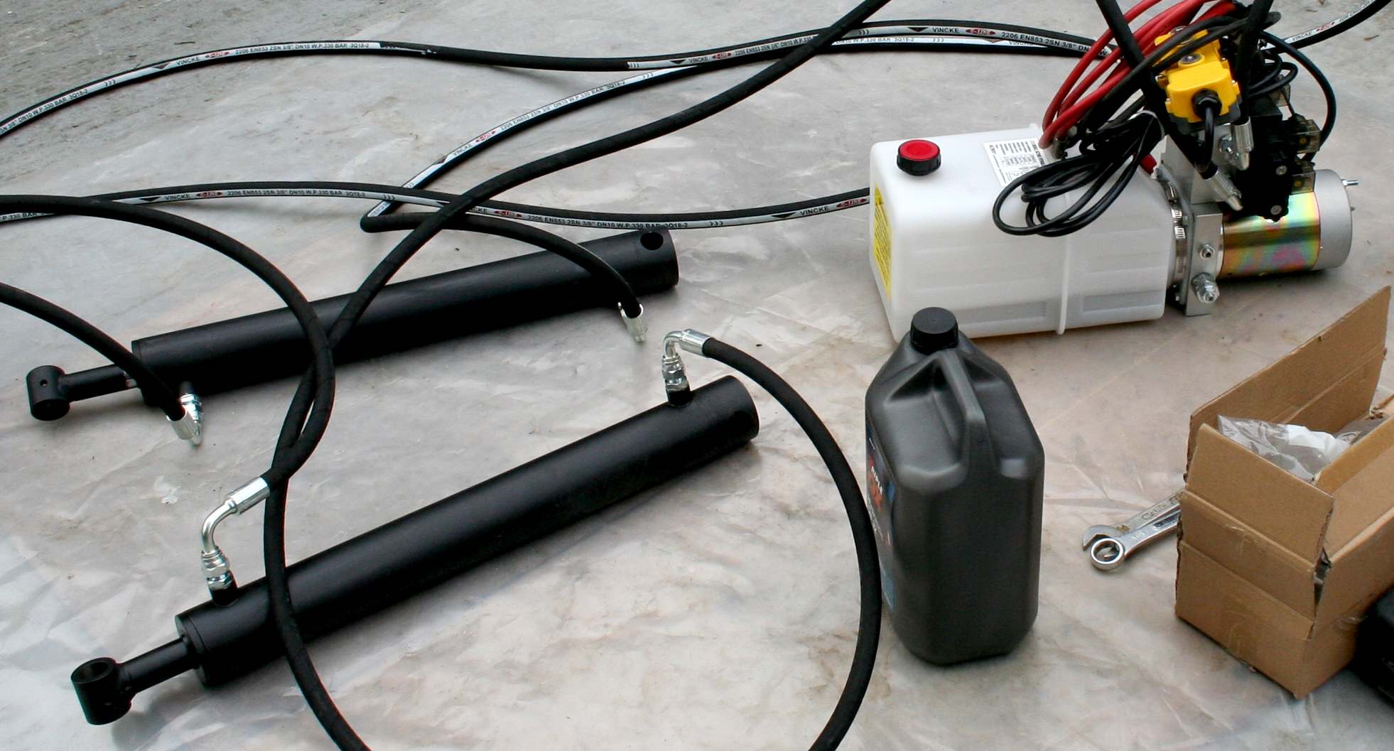
HYDRAULICS TEST - Lolita connected the power lifting rams to one of the hydraulic power packs to work out the wiring for the Raspberry pi micro computer. We used five liters of a quality ISO 32 grade oil. As you can see from the reservoir level, we will need to top this up with another five liters in operation for when the rams are fully extended. Power came from two heavy duty leisure batteries. The test went well with no leaks. Copyright photograph © 6-05-19 Cleaner Ocean Foundation Ltd, all rights reserved.
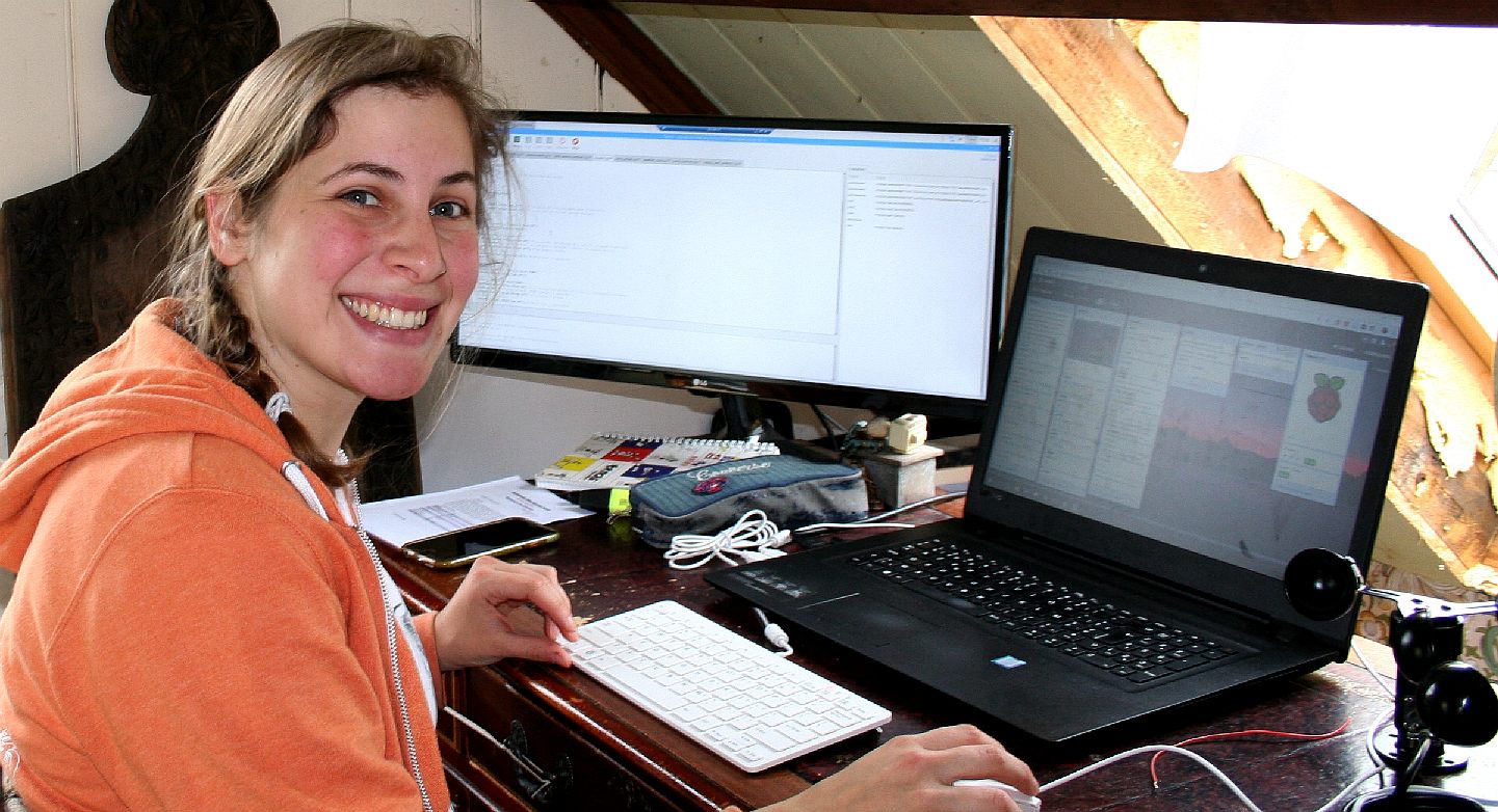
PROGRAMMING - It's a lot of hard work, building a program to read all the elements needed to control an energy harvesting station. Some code is available as free source, but most of what is needed to make a workable solution has to be custom written. Copyright © diagrams 9 May 2019. All rights reserved, Cleaner Ocean Foundation Ltd.
PAINTING - Before the frame could be mounted on the Transit, it had to be primed and painted. The vehicle is likely to be subject to salt laden sea spray over the next 24 months or more depending on how long the experiment needs to be land based. Copyright photograph © 12-05-19 Cleaner Ocean Foundation Ltd, all rights reserved.
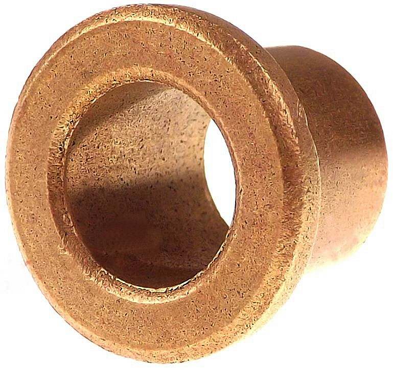
BEARINGS - We had to decide between phosphor-bronze and balls bearings for the wind turbine masts, with the bronze being lighter and less expensive, but likely to wear quicker. The alternative ball bearing unit weighs more where it counts aloft, but may be worth the extra in return for a longer working life and more responsive wind tracking.
CHAINS AND SPROCKETS - A very efficient and low cost way of transferring movement is using chains. They are manufactured in a variety of sizes off the shelf. We will be using chain drive to synchronize wind turbine position to limit interference, though some trailing and leading is inevitable at certain headings.
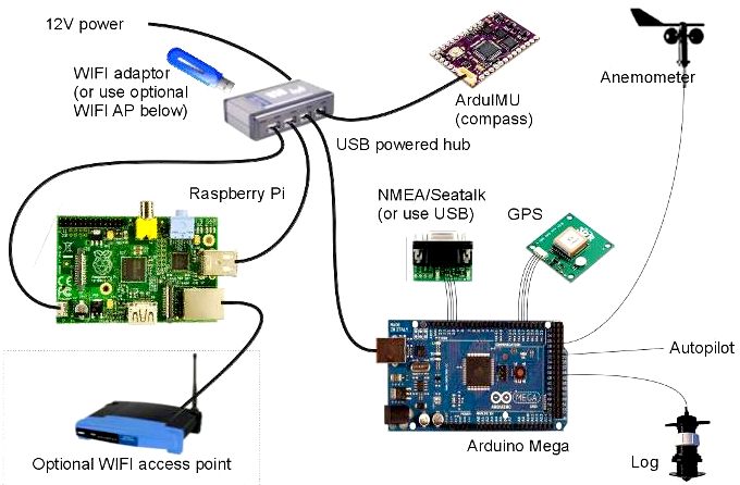
To control the hydraulics, hence the position of the wind turbines in relation to the solar panels and wind speed, Lolita D'Ortona will be programming microcontrollers like the Raspberry Pi and Arduino computers that have a good selection of accessories and expansion boards to be able to communicate with an anemometer and other environmental sensors. Her remit is limited to wind turbine control. Solar panel control will be for another student to build on Lolita's work, perhaps next year, when we hope to be able to begin work on a coastal test-rig.
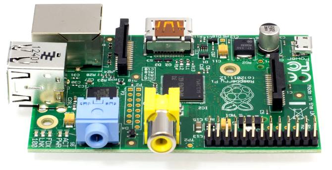
RASPBERRY - The Raspberry pi micro computer was originally designed in Cambridge and manufactured in Wales in the UK. The raspberry pi is looking to be a catalyst towards solving the world’s computing issues by educating and empowering today’s youth about programming. The raspberry pi foundation is a non-profit organization that spent 6 years developing their first raspberry pi. Raspberry pi is a computer the size of a credit card designed to encourage mainly kids into coding computers at pocket money prices. We are using the Pi model 3 A+ and model B units to control the wind turbine boom, linked to an anemometer to sense wind speed.
The software is open-source, chip manufacturers have kept their prices low, and the majority of the profits are funneled towards improving the devices and creating incentives to get students programming rather than envelope them in ready-made tech such as to help creativity thrive.
ARDUINO
- Arduino
is an open-source electronics prototyping platform based on
flexible, easy-to-use hardware and software. Arduino projects
can be stand-alone or they can communicate with software
running on a computer
(e.g. Flash, Processing, MaxMSP). Arduino is a
single-board microcontroller to make using electronics in
multidisciplinary projects more accessible. The hardware
consists of an open-source hardware board designed around an
8-bit Atmel AVR microcontroller, or a 32-bit Atmel ARM. The
software consists of a standard programming language compiler
and a boot loader that executes on the microcontroller.
WHY GO HIGHER?
Wind
speed increases as the height from the ground increases,
mainly due to the decrease in the friction produced by land
terrain deflections altering direction. As friction increases,
wind loses its kinetic energy in overcoming the friction and
decreases speed. Whereas the higher one goes, the friction
decreases significantly making the winds flow free of
interference. Generally, wind blows over the sea at higher
speeds than over land.
Centrifugal force is relatively minor in large-scale motions. The pressure gradient is usually dominant. In geostrophic wind equations (assuming balance between PG and Coriolis), the pressure gradient is divided by density, which decreases with height.
At sea level, air density is roughly 1 kg/m3. At around 5.5 km above sea level air density is 0.5 kg/m3. Since the PG is being divided by density, you get twice the velocity at 5.5 km altitude with the same pressure gradient.
Wind speeds don’t continue to increase with height all the way to space because the pressure gradient begins to relax in the stratosphere as you get far above the surface influences that drive weather.
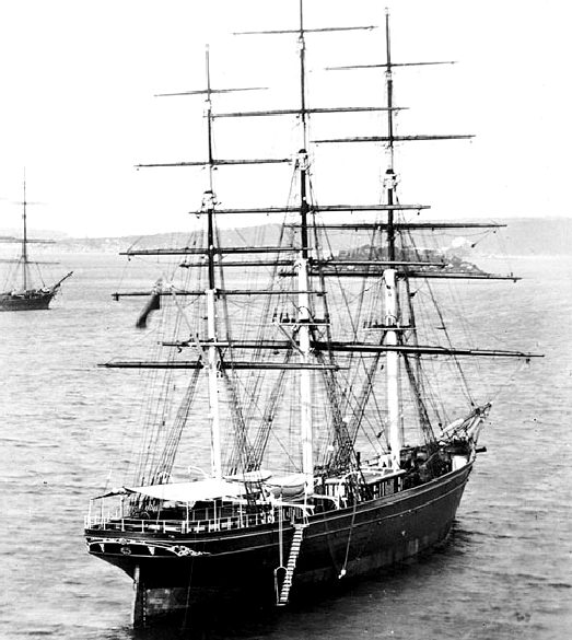
CLIPPER
SHIPS - A clipper was a very fast sailing ship of the middle third of the 19th century. Developed from a type of schooner known as Baltimore clippers, clipper ships had three masts and a square rig. The boom years of the clipper ship era began in 1843 as a result of a growing demand for a more rapid delivery of tea from China.
Donald McKay's 'Sovereign of the Seas' reported the highest speed ever achieved by a sailing ship – 22 knots (41 km/h), made while running her easting down to Australia in 1854.
The Cutty Sark was (survives as an exhibit in London) a British clipper ship. Built on the River Clyde in 1869 for the Jock Willis Shipping Line, she was one of the last tea clippers to be built and one of the fastest.
The maximum logged speed for Cutty Sark was 17.5 knots (32.4 km/h; 20.1 mph). Her greatest recorded distance in 24 hours was 363 nautical miles (672 km; 418 mi) averaging 15 knots (28 km/h; 17 mph).
OCEAN CONDITIONER - This vessel is designed to operate in fleets to target ocean waste before it settles on the ocean floor where nobody can recover it. There is nothing like it in existence today. The concept relies on solar and wind power working in tandem. This is part of the challenge for the SeaVax team, in collaboration with academia and (we hope) corporations who want to help us make a difference.
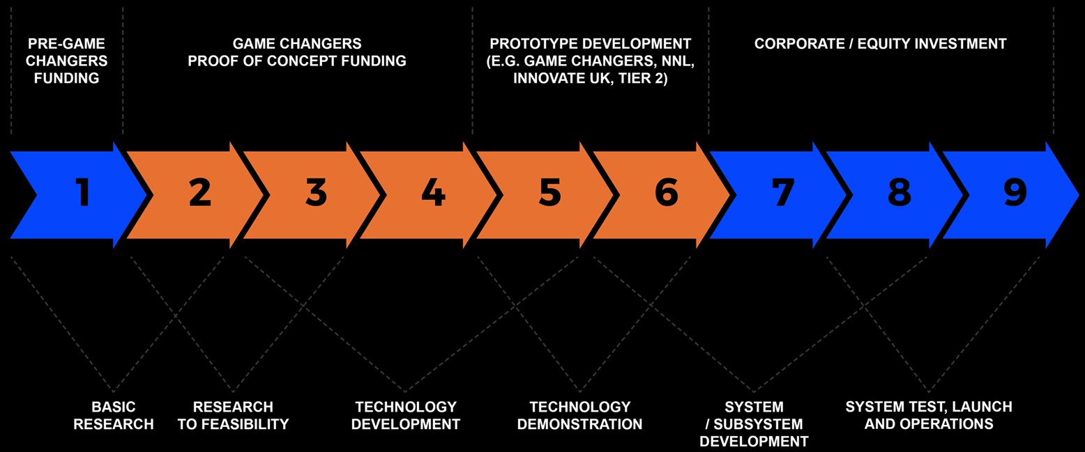
TRL 1 - TRL 2 - TRL 3 - TRL 4 - TRL 5 - TRL 6 - TRL 7 - TRL 8 - TRL 9 - TRL 10
TRL SCALE - The TRL scale is a metric for describing the maturity of a technology. The acronym stands for Technology Readiness Level. The scale consists of 9 levels. Each level characterises the progress in the development of a technology, from the idea (level 1) to the full deployment of the product in the marketplace after level 9.
In one study by Cristina L. Archer (carcher@UDel.Edu) and Mark Z. Jacobson (jacobson@stanford.edu) to quantify the worlds wind power potential using 80 meters as a viable wind energy collection height, the researchers concluded that even if only ~20% of the available global wind power could be captured, it could satisfy 100% of the worlds energy demand for all purposes and over seven times the world's electricity needs (1.6-1.8 TW).
USEFUL STUDY CONCLUSIONS
1.
Approximately 13% of all stations worldwide belong to class 3
or greater (i.e., annual mean wind speed ≥ 6.9 m/s at 80
m) and are therefore suitable for wind power generation. This
estimate is conservative, since the application of the LS
methodology to tower data from the Kennedy Space Center
exhibited an average underestimate of -3.0 and -19.8% for
sounding and surface stations respectively. In addition, wind
power potential in all areas for which previous studies had
been published was underestimated in this study.
LINKS & REFERENCE
https://www.gembloux.uliege.be/ https://www.parkersteel.co.uk/ https://www.r-techwelding.co.uk/ https://web.stanford.edu/group/efmh/winds/global_winds.html https://www.quora.com/Why-does-winds-velocity-increase-when-height-increases
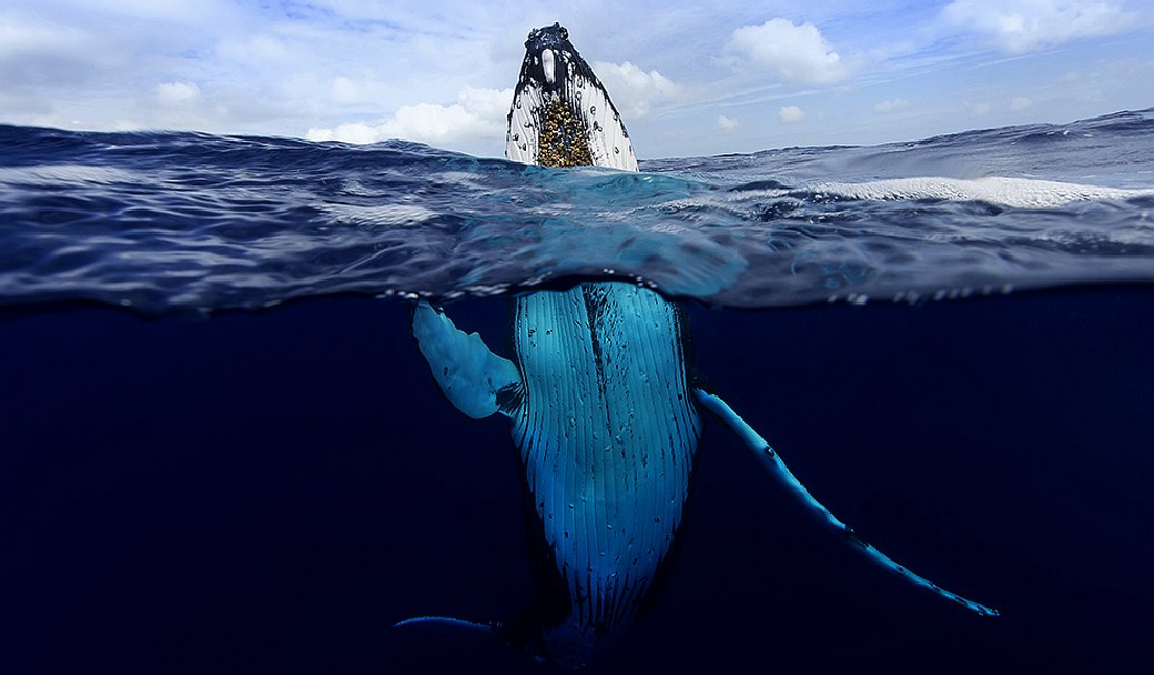
MARINE LIFE - This humpback whale is one example of a magnificent animal that is at the mercy of human activity. Humans are for the most part unaware of the harm their fast-lane lifestyles are causing. We aim to change that by doing all we can to promote ocean literacy to help reduce our plastic, food and carbon footprints.
ARRAYS - BOOM - MASTS - INTERIOR - PAINTING - ROBOTICS - WELDING - WIND TURBINES
This website is provided on a free basis as a public information service. Copyright © Cleaner Oceans Foundation Ltd (COFL) (Company No: 4674774) 2019. Solar Studios, BN271RF, United Kingdom. COFL is a charity without share capital. The names Amphimax™ RiverVax™ and SeaVax™ are trademarks.
|